Lecture 16 Theory of Lee & Shaffer
L 16.1 Theory of Lee & Shaffer
The theory of Lee & Shaffer was the result of an attempt to apply simplified plasticity analysis to the problem of orthogonal metal cutting. Certain assumptions regarding the behaviour of the work material under stress were made as follows:
1. The material is rigid plastic, which means that we elastic strain is negligible during deformation and that once the yield point is exceeded deformation takes place at constant stress.
2. The behaviour of the material is independent of the rate of deformation.
3. The effect of temperature increases during deformation is neglected.
4. The inertia effects resulting from the acceleration of the material during deformation are neglected.
5. Tooltip is sharp.
6. Continuous chip is formed.
7. Stress is uniform on the rake face (µ is constant).
The assumptions should closely approximate the actual behaviour of the material during cutting because of the very high stress and strain rate that occurs in the cutting process. It is known that the rate of work hardening of most metals decreases rapidly with increasing strain and that the effect of a high strain rate is to raise the yield strength of metal with respect to its ultimate stress. One approach to solving the problem in plasticity is to construct a slip line field.
Slip line field solution
In general, 3-D deformation problem is difficult to analyze. However, often it can be reduced to a 2-D (plane strain) problem.
Slip line field the theory is an approach that has been widely used for the solution of plain strain problems. It is based on the fact that any general state of stress in-plane strain consists of pure shear and hydrostatic pressure. The slip lines are lines of maximum shear stress and show the direction of shear yield strength in pure shear at a given point. They come in orthogonal pairs and are designated as ɳ and β lines.
The silent properties of the slip line are as follows:
a. Shear strain is maximum along the slip lines.
b. A linear strain is zero along the tangent to the slip lines.
c. Slip lines may, in general, be curved, but if the stress distribution in the deformation zone is uniform then they are represented as straight lines.
d. The tangents of ɳ and β lines, i.e. the directions of maximum shear stresses make an angle π/4 with the direction of principal stresses.
e. The line of action of the algebraically largest principal stress lies in the first and third quadrants.
f. On the free surface, there can be no normal stress therefore σ 3 = 0. Assuming be hydrostatic compressive stress on all the faces of an element of the free surface equal to “ρ”.
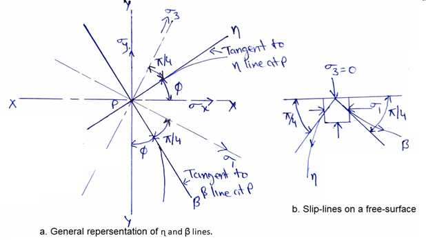
Fig. 16.1 Slip line field
Lee & Shaffer’s Shear Angle Relation
Several shear angle relations based on slip line field approach have been developed. The earliest and the simplest of all of them proposed by Lee & Shaffer in 1951.
They assume that the material ahead of the tool is ideally plastic and that the shear plane coincides with the direction of maximum shear stress.
The further assumed that is slip field exists within the chip to transmit the cutting forces from the shear plane to the tool face.
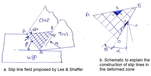
Fig. 16.2 Lee & Shaffer’s slip line field
By the figure 16.2 chip shear in-plane OA, it retains some shearing stress in a certain deformed zone OAB and only in the plane AB the sharing becomes complete, i.e. plane AB is a free surface on which the shear stress and normal stress both are equal to zero. Hence, AB is a principal plane in which the principal stress is zero.
The following point regarding these slip line field shown in figure 16.2:
i. As par property ‘B’ off the slip lines, two sets of orthogonal slip line will emanate from a different point of AB at an angle π/4. Assuming uniform stress distribution in deformed zone OAB, the slip lines are shown as straight lines.
ii. As OA is assumed to be coincident with the direction of maximum shear stress and AB is coincident with the direction of one of principle stress angle OAB = 45.
iii. In view of ‘i’ & ’ii’ above, one set of slip lines emanating from points of AB must be incident on OA at a right angle to it. Further, considering property ‘e’ off the slip lines, this set of slip lines must be associated with the algebraically largest principal stress. As one of the principal stress that lies among the free surface AB is zero, the other perpendicular to it will be equals 2τ.
Determination of Shear Angle by Mohr’s Circle
1. Let us consider an element ‘abc’ in plain AB and another element ‘def’ on the tool face.
2. If the mohr’s circle is drawn for the state of stress in the deformed on ‘OAB’, the centre of the circle where the shear and normal stress are both zero will be represented the stress in-plane ‘b’ of element ‘abc’.
3. Plane ‘a’ of element ‘abc’ and ‘d’ of element ‘def’ are inclined to ‘b’ at π/4 in the positive direction.
4. Accordingly, their state of stress is represented by the point (a,d) on the mohr’s circle.
5. Similarly, the state of stress of plane ‘c’ & ‘f’ that are inclined to ‘b’ at π/4 in the negative direction.
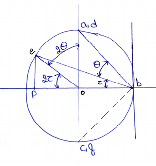
Fig. 16.3 Mohr’s circle representing the state of stress in the deformed zone
6. The stress is at the tool face are given by plane ‘e’ of element ‘def’. Since plane ‘e’ makes angle θ with plane ‘d’, the location of point ‘e’ on the mohr’s circle is obtained by drawing a line making angle 2θ with line [o, (a, d)].
7. Applying the theorem that the angle subtended by a chord at the centre of a circle is twice the angle subtended by it at the periphery. We observe that:
a. Angle [(a, d), o, e] = 2θ
b. Angle [(a, d), b, e] = θ
8. The coordinate of point ‘e’ gives shear angle stress (frictional) and the abscissa the normal stress on the tool face.
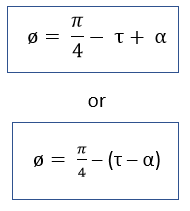
9. Hence, the friction angle ‘τ’ is found from the following relation:
10. From the Mohr’s circle

11. From the geometrical construction of the deformed zone
Ø = θ + α
12. substituting the value of θ in the above equation