Lecture 17 Friction in Metal Cutting
L 17.1 Friction in Metal Cutting
It is clear from the preceding discussion that, by some mechanism not completely understood, the frictional behaviour on the tool face affects the geometry of the cutting process. Before the frictional conditions in metal cutting are considered, it is necessary to discuss the nature of friction between dry sliding surfaces.
Amontons ' laws of friction, formulated in 1699, state that friction is independent of the apparent area of contact and proportional to the normal load between the two surfaces. In 1785, Coulomb verified these laws and made a further observation, that the coefficient of friction is substantially independent of the speed of sliding. The work of Bowden and Tabor has contributed much to the explanation of these empirical laws.
Microscopic examination shows that even the most carefully prepared "flat" metallic surfaces consist of numerous hills and valleys. When two surfaces are placed together, contact is established at the summits of only a few irregularities (asperities) in each surface (Figure 17.1a). If a normal the load is applied, yielding occurs at the tips of the contacting asperities, and the real area of contact Ar increases until it is capable of supporting the applied load. For the vast majority of engineering applications, this real area of contact, Ar is only a small fraction of the apparent contact area Aa and is given by
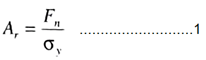
Where Fn is the normal force, and σy is the yield pressure of the softer metal.
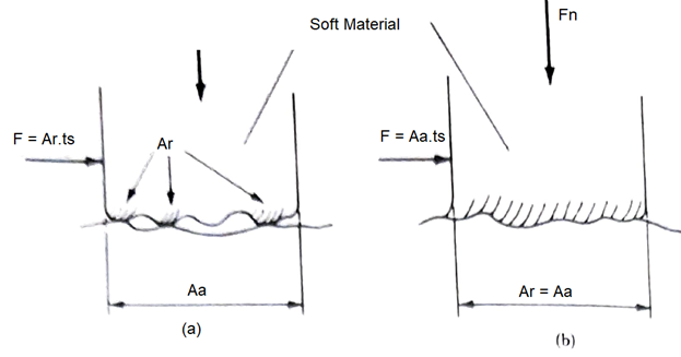
Fig. 17.1 Suggested frictional behaviour for a soft material, Where F = frictional force, Fn = normal force, Ar = real area of contact, Aa = apparent is of contact and τs = Shear strength of the softer metal. (a) Sliding friction; (b) Sticking friction.
The adhesion resulting from the intimate metallic contact of these asperities has been termed welding, and when sliding takes place, a force is required for continual shearing of the welded junctions at the tips of these asperities. The total frictional force F is therefore given by

Where τs is the shear strength of the softer metal.
Thus, from Equation 1 and Equation 2 the equivalent coefficient of friction is given by
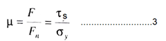
Equation 3 shows that the coefficient of friction is independent of the apparent contact area and since the ratio τs/σy would be expected to be Substantially constant for a given metal, the frictional force is proportional to the normal load (i.e., μ is constant). These results are consistent with the laws of dry sliding friction.
During metal cutting. It has generally been observed that the mean coefficient of friction between the 'chip and tool can vary considerably and is affected by changes in cutting speed, rake angle, and so on. This variance of the mean coefficient of friction results from the very high normal pressures that exist at the chip-tool interface. For example, when steel is machined, these normal pressure can be as high as 3.5 GN/m2 and can cause the real area of contact to approach, or become equal to, the apparent contact area over a portion of the chip tool interface (i.e., Ar/Aa = equals unity). Thus, under these circumstances, Ar has reached its maximum value and is constant. The frictional force F is still given by Equation 2 but is now independent of the normal force Fn, and the ordinary laws of friction no longer apply. Under these conditions, the shearing action is no longer confined to surface asperities but takes place within the body of the softer metal (Figure 17.1).
Consideration of frictional behaviour in metal cutting has led to the model of orthogonal cutting with a continuous chip and no built-up edge shown in Figure 17.2. Here the normal stresses between the chip and the tool are sufficiently high to cause Ar/Aa to approach unity over the region of length lst adjacent to the tool cutting edge, termed the sticking region. In the length lf –lst extended from the end of the sticking region to the point where the chip loses contact with the tool, the ratio Ar/Aa is less than unity, and therefore the coefficient of friction is constant: this region has been termed the sliding region.
ln previous work, evidence of the sticking mode of frictional contact was produced by examination of the undersurface of the chip on specimens where the cutting action had suddenly been stopped. It was observed that in a region adjacent to the tool cutting edge, the grinding marks on the tool, the face was imprinted on the undersurface of the chip, indicating that no relative motion between the chip and the tool had occurred and that the real and apparent area of contact is equal in this region. These observations have been confirmed optically using transparent sapphire tools and high-speed photography.
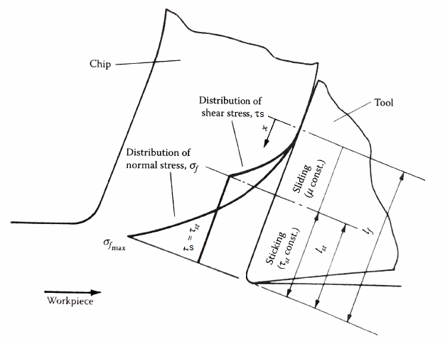
Fig. 17.2 Model of the chip-tool friction in orthogonal cutting, where σfmax = Max. normal stress, σf = normal stress, τs = shear stress, τst = Shear strength of the chip material in the sticking region, lf =chip-tool contact length, lst = length of sticking region
Under conditions of sticking friction, the means the angle of friction on the tool face will depend on the form of the normal stress distribution, the chip-tool contact length If, the mean shear strength of the chip material in the sticking region, and the coefficient of friction in the sliding region. Clearly, a single value of the mean angle of friction is insufficient to describe completely the frictional conditions on the tool face.
An analysis of the stress distribution on the tool face shown in Figure 17.2 has been presented by Zorev. It was shown that the mean angle of friction is mainly dependent on the mean normal stress on the tool face, and this result may be used to explain the effect of changes in working normal rake α on the mean friction angle τ. As α increases, the component of the resultant tool force normal to the tool face will decrease, and the ref ore the mean normal stress will decrease. However, the mean shear stress remains roughly constant and therefore an increase in α would be expected to increase the mean angle of friction τ. This result is in accordance with the findings of experimental work where an increase in α has been shown to result in an increase in τ for a wide variety of work materials. The general form of the rake face stress distributions shown in Figure 17.2 has been observed experimentally from photo-elastic measurements and using split-tool dynamometers. These methods do not allow the stresses to be determined very close to cutting edge, but there is evidence to indicate that the normal stress may be constant in the sticking region close to the cutting edge.